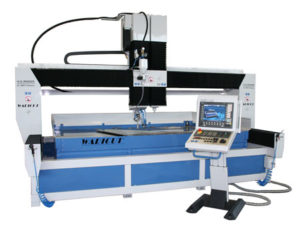
WARICUT HWM
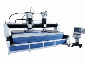
Our WARICUT® water jet systems from the HWM series fulfil maximum precision requirements. High quality components, good machining and of course service life – also in multiple shift operation – are decisive for the quality of all WARICUT® series. These characteristics convince our customers world wide.
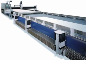
The HWM machine type is based on a welded, stable tubular frame construction made of steel. In order to ensure the desired precision of the machine, every frame is annealed with low stress, the guide tracks are first milled and then ground or planed. All axes consist of precision ball screw spindles and linear guides. Every machine is of course measured with a laser interferometer and the precision documented before it leaves the factory.
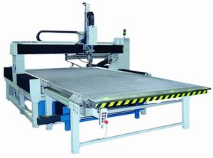
Machine frame and cutting basin are usually separated for all types in order to rule out thermal influences on the machine geometry due to heating of the cutting basin.
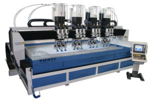
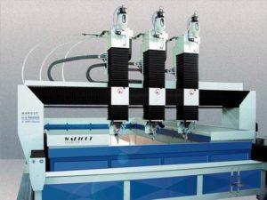
Waricut HWM – Examples of possible expansions
Every machine is individually designed according to customer requirements as single or multiple head system in 2D or 3D (or a combination). There is, of course, also a choice of interesting additional equipment options such as, for example, sliding tables or double shuttle tables. Due to the modular design of our systems, any of the optional functions provided by H.G. Ridder GmbH can be retrofitted at any time.
Would you like some advice? We are pleased to make you an offer for the machine of your choice.
The HWE machine type is available in the following sizes:
| X (mm) | Y (mm) 1 | Y (mm) 2 | Y (mm) 3 | Y (mm) 4 |
|---|---|---|---|---|
X (mm) | Y (mm) | |||
| 1200 | 1200 | |||
| 1550 | 2050 | |||
| 2050 | 1550 | 3050 | 4050 * | |
| 3050 | 2050 | 3050 | 4050 * | 5050 * |
| 4050 | 2050 | 3050 | 4050 * | 5050 * |
| 6050 | 2550 | 3050 | 4050 * | 5050 * |
| 9050 | 2550 | 3050 | 4050 * | 5050 * |
* Double arbour cross bar
Maschinenmaße (HWM‑P)
| Beschreibung | Maschinenmaße |
|---|---|
| Position deviation PA | <± 0,020 mm |
| Average position spread PS | <± 0,015 mm |
| Stroke cutting head axis (Z) |
|
According to VDI/DGQ3441, the position deviation contains systematic errors (e.g. geometry errors), while the average position scatter band only records random errors. The information relates to a measuring length of 1 metre (RT=20°+1°C)